
温度传感器LM35
LM35 是由National Semiconductor 所生产的温度传感器,其输出电压与摄氏温标
呈线性关系,转换公式如式,0 时输出为0V,每升高1℃,输出电压增加10mV。
LM35 有多种不同封装型式,外观如图所示。在常温下,LM35 不需要额外的校准
处理即可达到 ±1/4℃的准确率。 其电源供应模式有单电源与正负双电源两种,其接
脚如图所示,正负双电源的供电模式可提供负温度的量测;两种接法的静止电流-
温度关系如图 所示,在静止温度中自热效应低(0.08℃),单电源模式在25℃下静止电流约50μA,工作电压较宽,可在4—20V的供电电压范围内正常工作非常省电。

|
TO-92封装引脚图 SO-8 IC式封装引脚图 |
|
|


TO-46金属罐形封装引脚图 TO-220 塑料封装引脚图
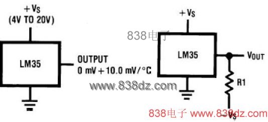
单电源模式 正负双电源模式
供电电压35V到-0.2V
输出电压6V至-1.0V
输出电流10mA
指定工作温度范围
LM35A -55℃ to +150℃
LM35C, LM35CA -40℃ to +110℃
LM35D 0℃ to +100℃
|
封装形式与型号关系 |
|
| TO-46金属罐形封装引脚图 | LM35H,LM35AH,LM35CH,LM35CAH,LM35DH |
| TO-220 塑料封装引脚图 | LM35DT |
| TO-92封装引脚图 | LM35CZ,LM35CAZ LM35DZ |
| SO-8 IC式封装引脚图 | LM35DM |
Electrical Characteristics电气特性(注 1, 6)
| Parameter 参数 |
Conditions 条件 |
LM35A | LM35CA | Units (Max.)
单位 |
||||
| Typical 典型 | Tested Limit 测试极限(注4) |
Design Limit设计极限(注5) |
Typical典型 |
Tested Limit 测试 |
Design Limit设计极限(注5) | |||
| Accuracy 精度 (注7 ) |
TA=+25℃ | ±0.2 | ±0.5 | - | ±0.2 | ±0.5 | - | ℃ |
| TA=−10℃ | ±0.3 | - | - | ±0.3 | - | ±1.0 | ℃ | |
| TA=TMAX | ±0.4 | ±1.0 | - | ±0.4 | ±1.0 | - | ℃ | |
| TA=TMIN | ±0.4 | ±1.0 | - | ±0.4 | - | ±1.5 | ℃ | |
| Nonlinearity非线性(注8) | TMIN≤TA≤TMAX | ±0.18 | - | ±0.35 | ±0.15 | - | ±0.3 | ℃ |
| Sensor Gain传感器增益(Average Slope)平均斜率 | TMIN≤TA≤TMAX | +10.0 | +9.9, | - | +10.0 | - | +9.9 | mV/℃ |
| - | - | +10.1 | - | - | - | +10.1 | ||
| Load Regulation 负载调节(注3) 0≤IL≤1mA | TA=+25℃ | ±0.4 | ±1.0 | - | ±0.4 | ±1.0 | - | mV/mA |
| TMIN≤TA≤TMAX | ±0.5 | - | ±3.0 | ±0.5 | - | ±3.0 | mV/mA | |
| Line Regulation 线路调整( 注3) | TA=+25℃ | ±0.01 | ±0.05 | ±0.01 | ±0.05 | - | mV/V | |
| 4V≤VS≤30V | ±0.02 | - | ±0.1 | ±0.02 | ±0.1 | mV/V | ||
| Quiescent Current 静态电流(注9) | VS=+5V, +25℃ | 56 | 67 | - | 56 | 67 | - | μA |
| VS=+5V | 105 | - | 131 | 91 | - | 114 | μA | |
| VS=+30V, +25℃ | 56.2 | 68 | 56.2 | 68 | - | μA | ||
| VS=+30V | 105.5 | 133 | 91.5 | - | 116 | μA | ||
| Change of Quiescent Current 变化静态电流 (注3) |
4V≤VS≤30V, +25℃ | 0.2 | 1.0 | - | 0.2 | 1.0 | - | μA |
| 4V≤VS≤30V | 0.5 | - | 2.0 | 0.5 | 2.0 | μA | ||
| Temperature Coefficient of Quiescent Current 静态电流/温度系数 | - | +0.39 | - | +0.5 | +0.39 | - | +0.5 | μA/℃ |
| Minimum Temperature for Rated Accuracy 最低温度 额定精度 | In circuit of Figure 1,IL=0 | +1.5 | - | +2.0 | +1.5 | - | +2.0 | ℃ |
| Long Term Stability 长期稳定性 | T J=TMAX,for 1000 hours | ±0.08 | - | - | ±0.08 | - | - | ℃ |
Electrical Characteristics电气特性(注 1, 6)
| Parameter 参数 | Conditions 条件 | LM35 | LM35C, LM35D | Units (Max)单位 | ||||
| Typical典型 |
Tested |
Design Limit 设计 极限 (注5) |
Typical典型 | Tested Limit 测试 极限 (注4) |
Design Limit 设计 极限 (注5) |
|||
| Accuracy,精度 LM35, LM35C (注7) | TA=+25℃ | ±0.4 | ±1.0 | - | ±0.4 | ±1.0 | - | ℃ |
| TA=−10℃ | ±0.5 | - | - | ±0.5 | - | ±1.5 | ℃ | |
| TA=TMAX | ±0.8 | ±1.5 | - | ±0.8 | - | ±1.5 | ℃ | |
| TA=TMIN | ±0.8 | - | ±1.5 | ±0.8 | - | ±2.0 | ℃ | |
| Accuracy, 精度 LM35D (注7) | TA=+25℃ | - | ±0.6 | ±1.5 | - | ℃ | ||
| TA=TMAX | ±0.9 | - | ±2.0 | ℃ | ||||
| TA=TMIN | ±0.9 | - | ±2.0 | ℃ | ||||
| Nonlinearity 非线性(注8) | T MIN≤TA≤TMAX | ±0.3 | - | ±0.5 | ±0.2 | - | ±0.5 | ℃ |
| Sensor Gain 传感器增益(Average Slope) 平均斜率 | T MIN≤TA≤TMAX | +10.0 | +9.8, | - | +10.0 | - | +9.8, | mV/℃ |
| - | +10.2 | - | - | - | +10.2 | |||
| Load Regulation 负载调节(注3) 0≤IL≤1mA | TA=+25℃ | ±0.4 | ±2.0 | - | ±0.4 | ±2.0 | - | mV/mA |
| T MIN≤TA≤TMAX | ±0.5 | - | ±5.0 | ±0.5 | - | ±5.0 | mV/mA | |
| Line Regulation 线路调整(注3) | TA=+25℃ | ±0.01 | ±0.1 | - | ±0.01 | ±0.1 | - | mV/V |
| 4V≤VS≤30V | ±0.02 | - | ±0.2 | ±0.02 | - | ±0.2 | mV/V | |
| Quiescent Current 静态电流(注9) | VS=+5V, +25℃ | 56 | 80 | - | 56 | 80 | - | μA |
| VS=+5V | 105 | - | 158 | 91 | - | 138 | μA | |
| VS=+30V, +25℃ | 56.2 | 82 | - | 56.2 | 82 | - | μA | |
| VS=+30V | 105.5 | - | 161 | 91.5 | - | 141 | μA | |
| Change of Quiescent Current 变化静态电流(注3) | 4V≤VS≤30V, +25℃ | 0.2 | 2.0 | - | 0.2 | 2.0 | - | μA |
| 4V≤VS≤30V | 0.5 | - | 3.0 | 0.5 | - | 3.0 | μA | |
| Temperature Coefficient of Quiescent Current 静态电流温度系数 | - | +0.39 | - | +0.7 | +0.39 | - | +0.7 | μA/℃ |
| Minimum Temperature for Rated Accuracy 最低温度 额定精度 | In circuit of Figure 1,IL=0 | +1.5 | - | +2.0 | +1.5 | - | +2.0 | ℃ |
| Long Term Stability 长期稳定性 | T J=TMAX, for 1000 hours | ±0.08 | - | - | ±0.08 | - | - | ℃ |
注1: Unless otherwise 注d, these specifications apply: −55℃≤TJ≤+150℃ for the LM35 and LM35A; −40°≤TJ≤+110℃ for the LM35C and LM35CA; and
0°≤TJ≤+100℃ for the LM35D. VS=+5Vdc and ILOAD=50 μA, in the circuit of Figure 2. These specifications also apply from +2℃ to TMAX in the circuit of Figure 1.
Specifications in boldface apply over the full rated temperature range.
注2: Thermal resistance of the TO-46 package is 400℃/W, junction to ambient, and 24℃/W junction to case. Thermal resistance of the TO-92 package is
180℃/W junction to ambient. Thermal resistance of the small outline molded package is 220℃/W junction to ambient. Thermal resistance of the TO-220 package
is 90℃/W junction to ambient. For additional thermal resistance information see table in the Applications section.
注3: Regulation is measured at constant junction temperature, using pulse testing with a low duty cycle. Changes in output due to heating effects can be
computed by multiplying the internal dissipation by the thermal resistance.
注4: Tested Limits are guaranteed and 100% tested in production.
注5: Design Limits are guaranteed (but not 100% production tested) over the indicated temperature and supply voltage ranges. These limits are not used to
calculate outgoing quality levels.
注6: Specifications in boldface apply over the full rated temperature range.
注7: Accuracy is defined as the error between the output voltage and 10mv/℃ times the device’s case temperature, at specified conditions of voltage, current,
and temperature (expressed in ℃).
注8: Nonlinearity is defined as the deviation of the output-voltage-versus-temperature curve from the best-fit straight line, over the device’s rated temperature
range.
注9: Quiescent current is defined in the circuit of Figure 1.
注10: Absolute Maximum Ratings indicate limits beyond which damage to the device may occur. DC and AC electrical specifications do not apply when operating
the device beyond its rated operating conditions. See 注1.
注11: Human body model, 100 pF discharged through a 1.5kW resistor.
注12: See AN-450 “Surface Mounting Methods and Their Effect on Product Reliability” or the section titled “Surface Mount” found in a current National
Semiconductor Linear Data Book for other methods of soldering surface mount devices

单电源模式 电流-温度关系 正负双电源模式
LM35 温度控制器应用电路图

|
两线远程温度传感器电路(接地传感器) |
|
4-20 mA 电流源 (0℃ to +100℃) |
|
|


温度数字转换器(串行输出)(128摄氏度满量程)
 辽公网安备21120202000012